API binding plans
The API plans presented in this section are designed in accordance with API 682 3rd Edition / API 610 10th Edition. These are standard flush piping schemes that are widely used in industry. These plans can be modified to suit the needs of customers.
API Plan 01
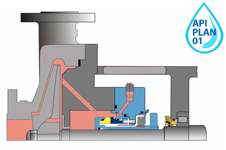
Description
Internal fluid circulation between stuffing box and pressure line, through a connecting channel
Purpose
Heat dissipation
API plan 02
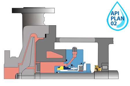
Description
It is implemented in "blind" stuffing boxes without circulation of flushing fluid.
Purpose
Heat dissipation
API Plan 11
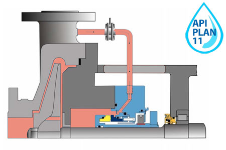
Description
Flushing the seal from the outlet to the seal chamber through the diaphragm
Purpose
Heat dissipation, evaporation reduction
API plan 12
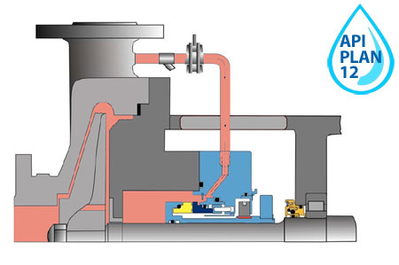
Description
According to API Plan 12, the product is circulated between the pressure line and the stuffing box through the coarse filter
Purpose
Heat dissipation, evaporation reduction
API plan 13
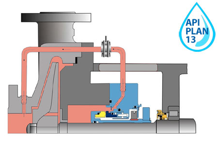
Description
Flushing the seal from the outlet to the seal chamber through the diaphragm
Purpose
Heat dissipation, recycling
API plan 14
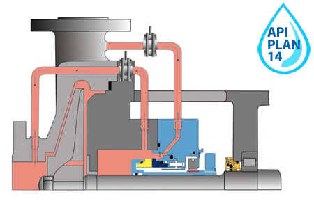
Description
Flushing the seal from the outlet to the seal chamber through the orifice and flushing the seal from the seal chamber to the inlet through the orifice
Purpose
Heat dissipation, recycling
API 682 plan 21
Scheme of the system for ensuring the operability of a single seal with fluid supply to the stuffing box from the pump pressure.
SINGLE MECHANICAL SEALS
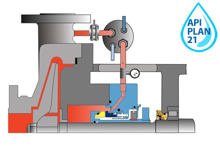
P1 - pump suction pressure
P2 - pressure in the stuffing box of the pump
P2 > P1, P2 > Ratm
Pos. Description
- Control valve
- Refrigerator (installed at an ambient temperature of more than 150 ... 200 ° C
- Mechanical seal type "UT"
- Stuffing box pump
- Pump
- Impeller
- Outlet temperature measurement
API plan 22

Description
Flushing the seal from the outlet to the seal chamber through the heat exchanger and pre-filter.
Purpose
Cooling
Application
Pumping high temperature products
API 682 Plan 23
Scheme of the system for ensuring the operability of a single seal with an impeller that circulates liquid through the stuffing box along an autonomous circuit.
SINGLE MECHANICAL SEALS
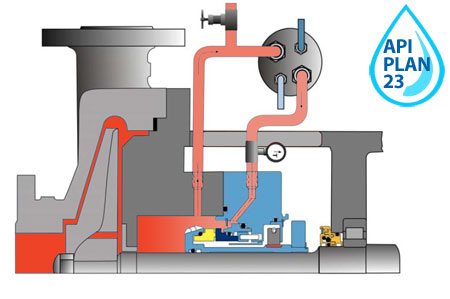
P1 - pump suction pressure
P2 - pressure in the stuffing box of the pump
P2 > P1, P2 > Ratm
Pos. Description
- Control valve
- Refrigerator (installed at an ambient temperature of more than 150 ... 200 ° C
- Mechanical seal type "UT"
- Stuffing box pump
- Pump
- Impeller
- Outlet temperature measurement
API Plan 31
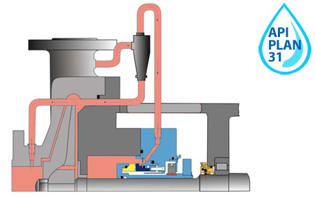
Description
Flushing the seal from the outlet to the seal chamber through the cyclone separator
Purpose
Heat removal, solids removal
Application
Pumping contaminated product
API 682 Plan 32
Schematic diagram of a single seal operability system with externally supplied "protective" fluid.
SINGLE MECHANICAL SEALS
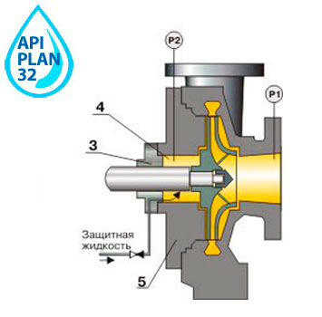
P1 - pump suction pressure
P2 - pressure in the stuffing box of the pump
P2 > P1, P2 > Ratm
Pos. Description
- Control valve
- Refrigerator (installed at an ambient temperature of more than 150 ... 200 ° C
- Mechanical seal type "UT"
- Stuffing box pump
- Pump
- Impeller
- Outlet temperature measurement
API plan 41
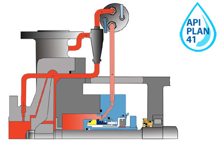
Description
Flushing the seal from the outlet to the seal chamber through the cyclone separator and heat exchanger
Purpose
Cooling and solids removal
Application
Pumping high temperature products containing solids
API plan 51
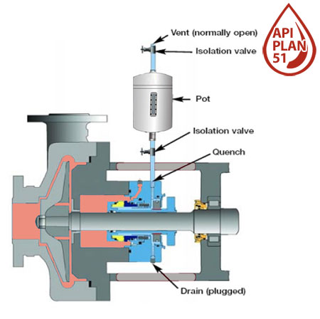
Description
API Plan 51 implements the supply of barrier coolant to the seal from an external reservoir without forced circulation.
Purpose
Redundant protective mechanical seal
Application
Liquids with high vapor pressure
API 682 plan 52
Schematic diagram of a tandem seal system with a reservoir
FOR TANDEM DOUBLE SEALS
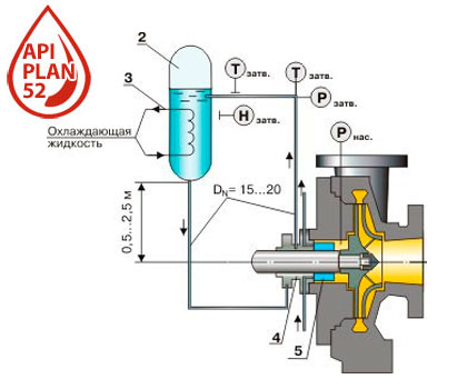
It is not necessary to pressurize the tank after it has been filled.
When the pressure in the stuffing box of the pump is less than the design pressure of the tank (4 MPa), the installation of a safety valve on the tank pipelines is not required.
Mechanical seals of the "tandem" type can be used both with a cooler at a temperature of the working medium of the pump up to 400 °C, and without it at a temperature of the working medium up to 150 °C.
Tohl = 5...30 °C
Gcool = 0.2…1.5 m3/h
| Pos. Description | Pos. Description |
| 1 Gas reducer | 6 Throttle |
| 2 Pressure tank | 7 Control valve |
| 3 Tank cooling system | P Pressure measurement |
| 4 Mechanical seal | T Temperature measurement |
| 5 Refrigerator seals | H Level measurement |
API 682 plan 53A
Schemes of systems for ensuring the operation of double mechanical seals and the "tandem" type
FOR DOUBLE SEALS
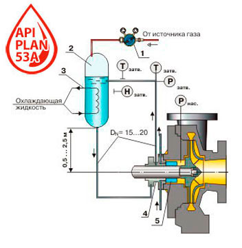
Schematic diagram of a double seal system with a reservoir. The system operates while maintaining the pressure of the barrier liquid (pressure in the tank) within the limits:
Rzatv \u003d Rnas + (0.1 ... 0.3) MPa
Gcool = 0.2…1.5 m3/h
At temperatures of the pump working medium up to 150°C, seals without a cooler are used, at temperatures of the pumped medium of 150...400°C - with a cooler.
| Pos. Description | Pos. Description |
| 1 Gas reducer | 6 Throttle |
| 2 Pressure tank | 7 Control valve |
| 3 Tank cooling system | P Pressure measurement |
| 4 Mechanical seal | T Temperature measurement |
| 5 Refrigerator seals | H Level measurement |
FOR PUMPS GROUP SEALS
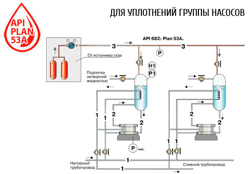
To service the seals of a group of pumps that perform the same task and are located close to each other, it is possible to use the system diagram below.
Рzatv \u003d Рnas + (0.1 ... 0.3) MPa
Р > Р1 - when feeding with gas
R< Р1 - при снятии давления газа
| Pos. Description |
| 1 Coolant pipe |
| 2 Barrier fluid pipeline |
| 3 Gas pipeline (nitrogen, air, etc.) |
| P Pressure measurement |
| H Level measurement |
API Plan 53B
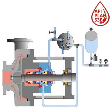
Description
Circulation of sealing liquid under increased pressure from a membrane accumulator through a reservoir
Purpose
Protection against the ingress of the pumped product into the environment
Application
Hazardous liquids at high pressure
API Plan 53C
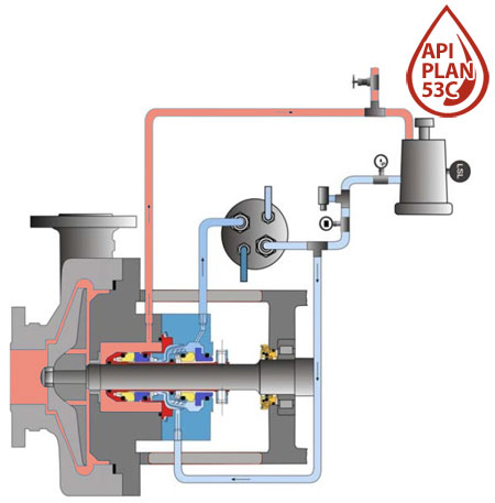
Description
Pressurized barrier fluid circulation from a piston accumulator through a reservoir
Purpose
Protection against the ingress of the pumped product into the environment
Application
Hazardous liquids, dynamic pressure control system
API 682 plan 54
Schemes of systems for ensuring the operation of double mechanical seals and the "tandem" type
FOR DOUBLE SEALS
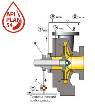
The most commonly used is the scheme of the system with the supply of barrier liquid from a separate pipeline with excess pressure m through the seal in a flow.
Rzatv \u003d Rnas + (0.1 ... 0.3) MPa
Тin = 5…30°С, Тout Ј 40°С
G = 0.2…1.0 m3/h
At temperatures of the pump working medium up to 150°C, seals without a cooler are used, at temperatures of the pumped medium of 150...400°C - with a cooler.
| Pos. Description | Pos. Description |
| 1 Gas reducer | 6 Throttle |
| 2 Pressure tank | 7 Control valve |
| 3 Tank cooling system | P Pressure measurement |
| 4 Mechanical seal | T Temperature measurement |
| 5 Refrigerator seals | H Level measurement |
FOR CONDENSATE PUMPS
Schematic diagram of a double seal operability system with fluid supply from the pump head and process piping
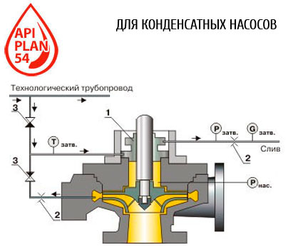
For condensate pumps, where dry operation of mechanical seals is not excluded, a guaranteed supply of barrier liquid can be carried out according to the above scheme.
Rzatv \u003d Rnas + (0.1 ... 0.3) MPa
Tzatzatv >= 0.2 m3/h
At temperatures of the pump working medium up to 150°C, seals without a cooler are used, at temperatures of the pumped medium of 150...400°C - with a cooler.
| Pos. Description | Pos. Description |
| 1 mechanical seal | P Pressure measurement |
| 2 Throttle | T Temperature measurement |
| 3 Check valve | G Flow measurement |
API plan 61
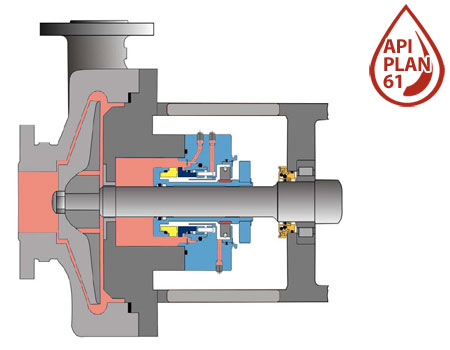
Description
On the API 61 plan, all fluid ports to the seal are plugged for later use on the API 62 and API 65 plans.
Purpose
Prevention of solids settling
Application
Pumping hot hydrocarbons, alkalis
API plan 62
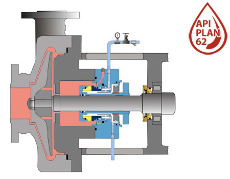
Description
Injection of an external fluid to be used for quenching and flushing/washing. The quench lubricates the seal contact surfaces on the air side, with vapour or water. The flushing/washing operation has a lubricating function.
Objetive
To guarantee seal lubrication, reducing the formation of particles between the contact surfaces due to carbonisation, oxidation or crystallisation.
Application
Horizontal or vertical pumps. Single seal layout. Fluids that crystallise when in contact with the atmosphere or generate solid deposit that block or stick to the seal faces.
API Plan 65
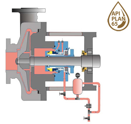
Description
API plan 65 allows you to determine the amount of leakage through the mechanical seal. In the event of a breakdown of the friction pair, the external tank of the piping is equipped with an upper level alarm that will work immediately as soon as the liquid level in the tank increases.
Purpose
For cases where the pumped product can condense from the atmospheric side;
API plan 71
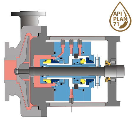
Description
In the API 71 plan, all fluid passages to the seal are plugged for later use with barrier gas.
Purpose
For subsequent application of API 72, API 75 and API 76 plans;
API plan 71

Description
Atmospheric buffer gas supply system
Purpose
Redundant protective mechanical seal
Purpose
Pumping hydrocarbon systems, typically used in conjunction with Plan 75 or Plan 76
API plan 74
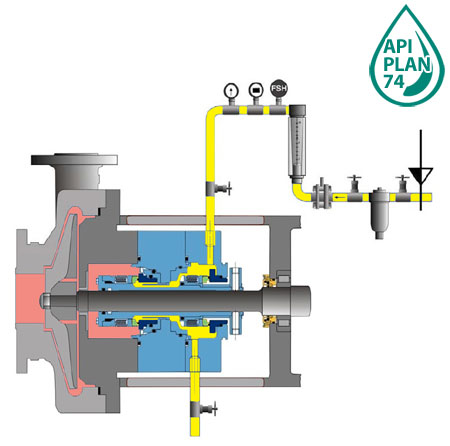
Description
Pressurized barrier gas supply system
Purpose
Protection against the ingress of the pumped product into the environment
Purpose
Hazardous liquids
API plan 75
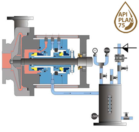
Description
Discharge to liquid collector and gas recovery system
Purpose
Collection of leaks
Purpose
Condensate leak
API plan 76
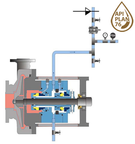
Description
Discharge to the gas utilization system
Purpose
Collection of leaks
Purpose
Leakage of non-condensable gases
This category does not contain any products.

