Pumps inline heating water supply

Dry Rotor Pumps IRG Series
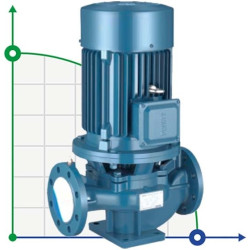
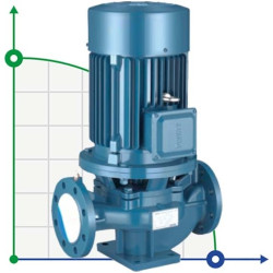
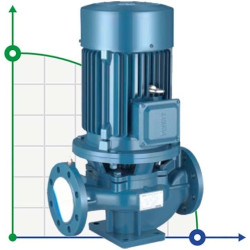
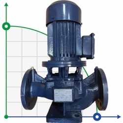
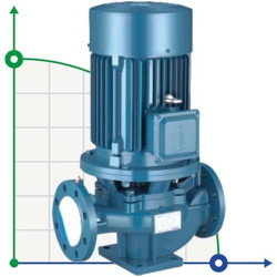
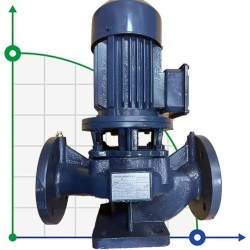
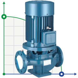
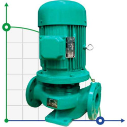
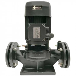
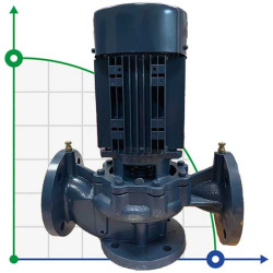
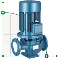
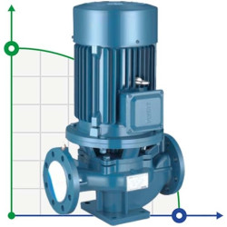
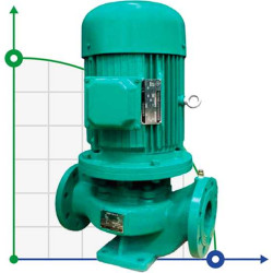
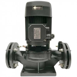
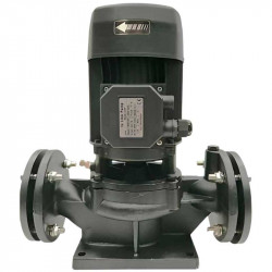
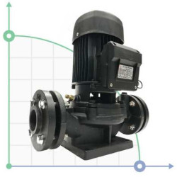
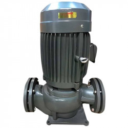
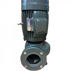
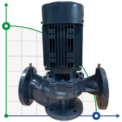
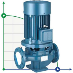
Dry Rotor Pumps IRG Series – vertical single-stage centrifugal pumps with in-line nozzles. This design of these pumps makes them more resistant to mechanical inclusions in the pumped liquid compared to similar pumps with a "wet" rotor. Their universal design ("in-line") allows quick dismantling of the pump from the pipeline without dismantling the elements of the pipeline system.
Characteristic
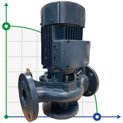
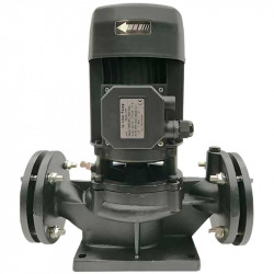
- Glanded cast iron pumps IRG have a vertically located electric motor, and the suction and pressure nozzles are located on the same axis, which allows them to be installed directly on the pipeline (in-line); pumps have compact overall dimensions, do not take up much space and can be installed outdoors (under a canopy);
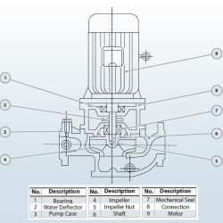
- The impeller of IRG dry rotor pumps is located directly on the extended motor shaft, thanks to which the pumps operate quietly without creating high vibrations, and the pump housing is connected to the motor in such a way that it can significantly reduce thrust during pump operation;
- A mechanical seal or a combination of different seals is used to seal the pump shaft; in addition, the titanium alloy from which the seal is made extends the life of the pumps.
Pump features
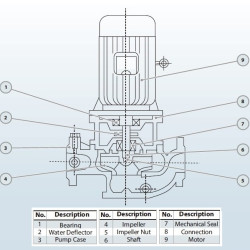
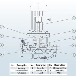
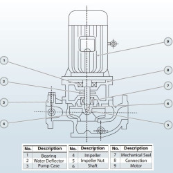
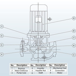
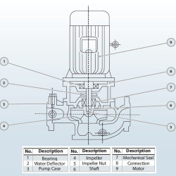
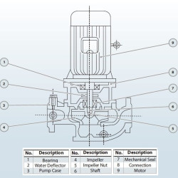
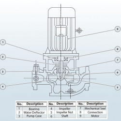
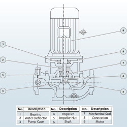
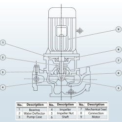
In a dry rotor, the pump part with the impeller has direct contact with the pumped medium. And the motor is separated from the pump part by a rotating shaft and a sliding mechanical seal. The mechanical seal is a dynamic seal and is used to seal the gap between the pump's rotating shaft and pump housing.
Model range of IRG pumps with a dry rotor made of cast iron
| Model | Consumption (m3/hour) |
pressure (m) |
Power (kW) |
turnovers (rpm) |
Diameter (mm) |
NPSN (mm) |
efficiency |
The weight (kg) |
| 50-125A | eleven | 16 | 1.1 | 2900 | fifty | 2.3 | 57 | 38 |
| 50-125(I)A | 22.3 | 16 | 2.2 | fifty | 2.5 | 66 | 48 | |
| 50-200(I)A | 23.5 | 44 | 5.5 | fifty | 2.5 | 57 | 107 | |
| 65-125 | 25 | twenty | 3 | 65 | 2.5 | 68 | 58 | |
| 65-160 | 25 | 32 | four | 65 | 2.5 | 63 | 75 | |
| 65-200 | 25 | fifty | 7.5 | 65 | 2.5 | 58 | 107 | |
| 65-250 | 25 | 80 | fifteen | 65 | 2.5 | fifty | 180 | |
| 80-125 | fifty | twenty | 5.5 | 80 | 3.0 | 72.5 | 99 | |
| 80-100(I) | 100 | 12.5 | 5.5 | 80 | 4.5 | 76 | 108 | |
| 80-125(I) | 100 | twenty | eleven | 80 | 4.5 | 76 | 163 | |
| 80-160 | fifty | 32 | 7.5 | 80 | 3.0 | 71 | 105 | |
| 80-200 | fifty | fifty | fifteen | 80 | 3.0 | 67 | 175 | |
| 100-100A | 89 | ten | four | 100 | 4.5 | 74 | 91 | |
| 100-160 | 100 | 32 | fifteen | 100 | 4.5 | 76 | 191 | |
| 100-200 | 100 | fifty | 22 | 100 | 4.0 | 74 | 245 | |
| 100-200(I) | 160 | fifty | 37 | 100 | 5.2 | 79 | 402 | |
| 200-315 | 200 | 32 | thirty | 1450 | 200 | 3.5 | 78 | 417 |
| 200-400A | 187 | 44 | 37 | 200 | 3.5 | 74 | 462 | |
| 200-250(I)A | 358 | 16 | twenty | 200 | 4.0 | 73 | 405 | |
| 200-315(I) | 400 | 32 | 55 | 200 | 4.0 | 80 | 675 | |
| 200-315(I)A | 374 | 28 | 45 | 200 | 4.0 | 79 | 560 | |
| 200-315(I)B | 346 | 24 | 37 | 200 | 4.0 | 78 | 535 |
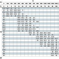
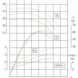
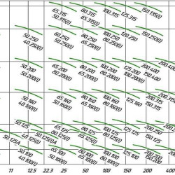
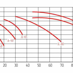
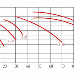
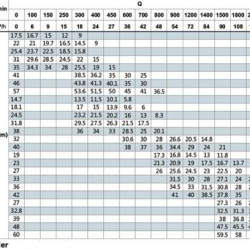
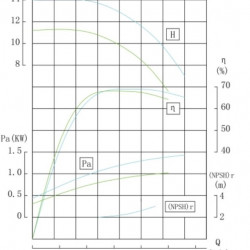
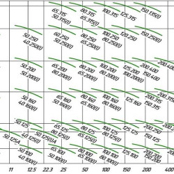
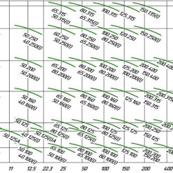
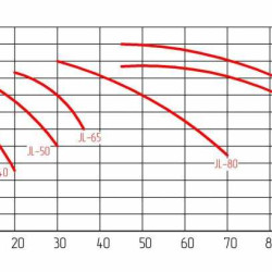
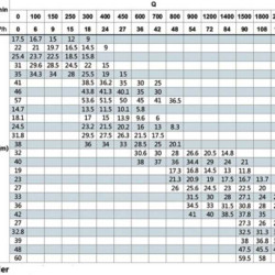
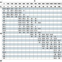
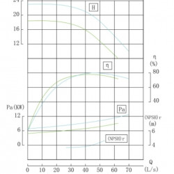
IRG Dry Rotor Pump Performance Diagrams

Specifications
| Pump data | materials | ||
|
Step no. pressure |
PIN 16 |
Frame Shaft Working wheel slip ends. seal casing |
cast iron |
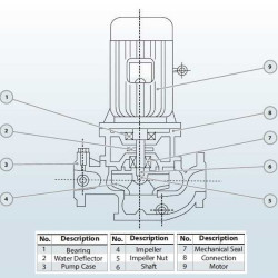
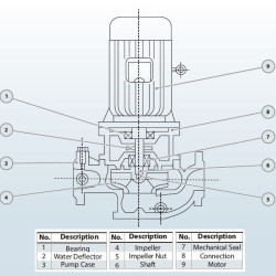
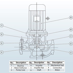
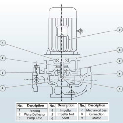
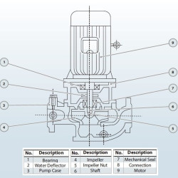
Pump Diagram


